PLEASE VISIT https://QualityMetalDecking.com for a QUOTE
Nationwide metal decking supplier specializing in fast delivery of B, N, and composite deck.
As described in the Steel Deck Institute Manual of Construction with Steel Deck:
METAL DECKING: In general, steel deck (cubierta de metal) is made by cold forming structural grade sheet steel into a repeating pattern of parallel ribs. The strength and stiffness of the panels are a result of the shape of the ribs and the material properties of the steel. Deck lengths can be varied to suit the job conditions, but because of shipping considerations, are usually less than 40′ long. Standard deck with varies with the product used, but full sheets are usually 12″, 18″, 24″, 30″, 32″ or 36″. Deck is typically furnished in a standard width with the ends square cut. Any cutting for width, such as at openings or for angular fit, is done at the job site.
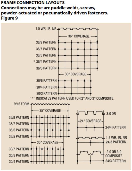
Deck is typically attached to the building frame with arc puddle welds, self drilling screws, or powder or pneumatically driven pins. Sheet to sheet fastening is done with screws, button punching (crimping), or welds.
COMPOSITE FLOOR DECK: After installation and adequate fastening, floor deck serves several purposes. It (a) acts as a working platform (b) stabilizes the frame (c) serves as a concrete form for the slab and (d) reinforces the slab to carry the design loads applied during the life of the building. Composite decks are distinguished by the presence of shear connector devices as part of the deck. These devices are designed to mechanically lock the concrete and deck together so that the concrete and deck work together to carry subsequent floor loads. The shear connector devices can be rolled into embossments, lugs, holes or wires welded to the panels. The deck profile configuration can also be used to interlock concrete and steel.
Composite deck finishes are either galvanized (zinc coated) or phosphatized/painted. Phosphatized/painted deck has a bare (phosphatized) top surface which is the side to be in contact with the concrete. The bare top surface can be expected to develop rust BEFORE CONCRETE is placed. The bottom side of the deck has a primer coat of paint. Galvanized deck has a zinc coating on both sides.
Composite metal floor deck (cubierta de metal) is normally installed so the panel ends do not overlap on the supporting beams. Shear lugs or profile shape often prevent a tight metal-to-metal fit if panel ends overlap. The air gap caused by overlapping prevents proper fusion with the structural steel when sheet end laps are shear stud welded.
Adequate end bearing of the deck must be obtained as shown on the erection drawings. If bearing is actually less than shown, further investigation is required.
ROOF DECK: Metal Roof deck (cubierta de metal) is not designed to act compositely with other materials. Roof deck acts alone in transferring horizontal and vertical loads into the building frame. Roof deck rib openings are usually narrower than floor deck rib openings. This provides adequate support of rigid thermal insulation board.
Roof deck is typically installed to endlap approximately 2″ over supports. However, it can be butted (or lapped more than 2″) to solve field fit problems. Since design professionals frequently use the installed deck system as part of the horizontal bracing system (the deck as a diaphragm), any fastening substitution or change should be approved by the design professional. Continuous perimeter support of the deck is necessary to limit edge deflection in the finished roof and may be required for diaphragm shear transfer.
Standard roof deck finishes are galvanized or primed painted. The standard factory applied paint for roof deck is primer paint, and is not intended to weather for extended time periods. Field painting, touch up of abrasions, and deterioration of the primer coat or other protective finishes are the responsibility of the buyer. It is recommended, however, that any field paint be applied over a small test area of the primed deck and tested for compatibility and adhesion prior to proceeding with field painting.
CELLULAR DECK: Cellular metal deck (cubierta de metal) is made by attaching a bottom steel sheet to a roof deck or composite floor deck panel. Cellular deck can be used in the same manner as floor deck. Electrical, telephone, and computer wires are easily run through the chase created between the deck panel and the bottom sheet.
When used as part of the electrical distribution system, the cellular deck must be installed so that the ribs line up and create a smooth cell transition at abutting ends. The joint that occurs at butting cell ends must be taped or otherwise protected to prevent concrete from entering the cell. Cell interiors must be free of welding burrs, or other sharp intrusions to prevent damage to wires.
When used as a metal roof deck (cubierta de metal), the bottom, flat plate is usually left exposed to view. Care must be maintained. during erection to keep good alignment and prevent damage.
Cellular deck is sometimes used with flat plate on the topside to provide a flat walking surface. Installation of deck for this purpose requires special methods for attachment to the frame because the flat plate now on the top can prevent direct access to the deck material that is bearing on the structural steel. It may be advisable to treat the flt top surface to prevent slipping. Cellular deck is always furnished galvanized or painted over galvanized.
FORM DECK: Form deck can be any floor or roof deck product used as a concrete form. Connections to the frame are by the same methods used to attach floor and roof deck. Welding washers are recommended when welding metal thickness is less than 0.0280 inches.
Form deck is furnished galvanized, prime painted, or uncoated. Galvanized deck must be used for those roof deck systems where form deck is used to carry a lightweight insulating concrete fill.
In a patented, dry installed roof deck assembly, form deck is utilized as the primary load carrying element. This assembly functions as a structural roof deck diaphragm. The assembly may include dry installed thermal insulation placed above either prime painted, field painted galvanized, or galvanized and painted steel sections.
COMPOSITE DECK PROFILES:
36″ Coverage, 3″ Deep Profile, Gauges – 22, 20, 18, or 16 (varying embossment patterns) – Equiv. Dek-ing
32″ Coverage, 3″ Deep Profile, Gauges – 22, 20, 18, or 16 (varying embossment patterns) – Equiv. Dek-ing
36″ Coverage, 2″ Deep Profile, Gauges – 22, 20, 18, or 16 (varying embossment patterns) – Equiv. Dek-ing
36″ Coverage, 1.5″ Deep Profile, Gauges – 22, 20, 18, or 16 (varying embossment patterns)
ROOF DECK PROFILES:
32″ Coverage, 3″ Deep Profile, Gauges – 22, 20, 18, or 16 (varying embossment patterns) – Equiv. Dek-ing
36″ Coverage, 1.5″ Deep Profile, Gauges – 22, 20, 18, or 16 (varying embossment patterns)
12″ Coverage, Deep Deck Profiles (4.5″, 6.0″, 7.5″), Gauges – 22, 20, 18, or 16 (varying embossment patterns)
APPROVED ERECTION DRAWINGS: Only those installation drawings that have been stamped “APPROVED FOR CONSTRUCTION” i.e. “FIEL D USE” should be used for deck erection. Prior to beginning deck erection, the erector should review the plans for overall job site orientation. On projects with multiple deck profiles and gages, individual areas should be identified for each type of metal deck (cubierta de metal). All General Notes should be reviewed for special instructions. Drawing sections in particular need to be studied for installation details. The drawings and bundle tags need to be examined for proper bundle placement. The engineer of record has approved the attachment method and pattern. Therefore, all fastening to the structure and sheet side laps should be carefully followed as shown on the “APPROVED FOR CONSTRUCTION” drawings.
PACKAGING: Deck is banded into bundles that can weigh several thousand pounds, but the deck bundle weight will be limited to a maximum 4,000 lbs. for deck to be applied to joists. Deck bundle weights for material to be applied over structural steel frames or other framing systems will be as required to suit job conditions, and to meet safe hoisting, spreading and installation procedures. If heavier or lighter bundles are required because of job conditions, this information must be conveyed to the deck supplier well before production is scheduled. The deck supplier, the erector, and the purchaser should all be in agreement about the bundle sizes, and weights that are to be delivered to the job.
LOADING AND SHIPPING: Bundle tags show the job area where the bundle belongs. The deck manufacturer may be asked to sequence deck bundling so that deck will be delivered in a proper (or previously agreed upon) order, and be unloaded and hoisted in logical sequence. Erection information should be made available to the deck manufacturer as soon as possible after placing the order so that sequencing can be done during preparation of approval drawings.
All job conditions that will affect shipping (i.e. weight restrictions, staging, special strapping, blocking, tarping) should be determined well in advance of fabrication so that appropriate steps can be taken by the shipper.
The deck manufacturer will load trucks using standard procedures. These procedures may consider the following:
1. Strapping will be secured, preventing blow off, or loosening of sheets during transit.
2. Deck bundles may be placed against the trailer or truck bulkhead to prevent forward movement in case of sudden stop. Note that load distribution may dictate another arrangement.
3. Deck bundles are separated with dunnage (horizontally and vertically) of at least 1-1/2″ (more if agreed upon), so that lifting slings can be inserted for unloading.
4. Deck will be loaded with the longest bundles on the bed of the truck to ensure that the load will be balanced.
5. To ensure safe and level loads, every other bundle may be turned on the truck. In all cases, the bundle arrangement on the trailer will be made with an effort to provide the greatest stability of the load, and to achieve the allowable weight.
During transportation, shock and vibration tends to compress bundles, which can result in slackening of the trailer load binders normally used in the transport of deck. This may cause a dangerous situation; over tightening of the tie downs in anticipation of settling will damage the product. Periodic adjustments and retightening are necessary. Each adjustment should also ensure that the tarps are repositioned to keep the load dry to prevent moisture from affecting the finish.
If less than truckload (LTL) shipments are used, the deck manufacturer cannot be responsible for any damage caused by rehandling or load transfer between trucking companies.
We ship nationwide. All our roof deck (1.5″ deep B-36 and 3″ deep N-32) and floor / composite deck (1.5″ deep BH-36, 2″ deep 2WH-36 and 3″ deep 3WxH-36) can ship to all 50 states.
RECEIVING, UNLOADING, STORAGE, AND PROTECTION:
RECEIVING –
There must be proper access to the structure for the deck delivery. The access must be adequate to support the lifting equipment and the delivery trucks. Lifting equipment must be capable of safely lifting the deck bundles, and have sufficient reach to properly place the bundles on the structure.
UNLOADING –
Material should be checked as it is received. Bundles should be counted. The bill of lading should be checked to verify trailer contents. Small packages are sometimes carried inside the tractor. Check to see if all items are present. Any material damages or shortages should be noted on the bill of lading PRIOR to signing for the material, and the suppler should be immediately notified.
STORAGE AND PROTECTION
If ground storage is needed, the deck bundles should be stored off the ground, with one end elevated to provide drainage. Bundles should be protected against condensation with a ventilated waterproof covering. Bundles should be stacked so that this is no danger of tipping, sliding, rolling, shifting, or material damage.
Bundles should be checked for tightness so wind cannot loosen sheets or work the bundles apart. Tightness should be periodically checked and additional securement should be used as needed. Bundles should never by hoisted by strapping, and should always be placed tag side up. It is the position of the Steel Deck Institute that; DECK BUNDLES MUST ALWAYS BE PLACED ON THE FRAME NEAR A MAIN SUPPORTING BEAM AT A COLUMN OR WALL. IN NO CASE, SHOULD THE BUNDLES BE PLACED ON UNBOLTED FRAMES, OR UNATTACHED OR UNBRIDGED JOISTS. The structural frame must be properly braced to receive the bundles.
OSHA Federal Register Subpart R 1926.757 does allows some flexibility as to how and when, during the structure’s erection process, landing bundles of deck permitted. This OSHA regulation must be examined by anyone engaged in this activity, such that all criteria is understood and met.
ERECTION OF DECK AND JOB SITE SAFETY
Serious injury or death can result from failure to familiarize and comply with all applicable safety requirements of federal, state and local regulations, and these safety guidelines before erecting steel deck.
OSHA Federal Register Subpart R 1926 issued January 18, 2002 provides specific erection guidelines for typical conditions. However, where employer elect, due to conditions specific to the site, to develop alternate means and methods that provide employee protection, a site specific erection plan shall be developed by a qualified person. OSHA provides guidelines for establishing a site specific erection plan in Appendix A of OSHA Federal Register Subpart R 1926. The deck manufacturer is not responsible for preparing the “site specific” erection plan. However, deck erection drawings may be helpful to those preparing the plan.
Deck erectors create their own working platform. For the most part these platforms will not have protected openings. Erectors must also work on the open steel frame and use ladders or scaffolding to access the work.
Coil ordering practices and manufacturing processes have been established and are being followed so that as shipped deck products will be free of visible liquid lubricants and dry residues will be minimized. The purpose of establishing these practices and processes is to reduce the slipping hazard of the walking surfaces of decking products. For more information on this issue, please refer to the “Steel Coalition Lubricant Task Group Report” dated May 14, 2002. This report is available on the SDI web site.
ALERTNESS
Most deck installations are done on an elevated structure and the danger of falling is always present. Falls may occur at any time, and at any location. Alertness is essential. Ladders should be securely tied to the structural frame or the scaffolding. Stairs, if available, should be rigidly attached to the building frame.
Access areas should be specially patrolled to keep them free of equipment, material, and debris.
Deck edges are SHARP. Workers should take precautions to protect themselves from share edges and projecting corners.
It is very important that the structure be ready to receive the deck. Before deck bundles are placed on the frame, the frame plumbness and connections should be checked. Verify that temporary bracing is in place to keep the frame in a plumb condition until the deck is placed and secured.
LIFTING
Steel Joists must be securely attached at their bearing ends and have their bridging completely attached. Verify the structure’s capacity to carry the deck bundles. The bundles must be rigged for lifting so that shifting and excessive tipping will not occur and so the lifting device will not damage the metal roof deck or metal floor deck (cubierta de metal). All lifting equipment must be adequate for the job. The hoisting operation must be properly directed and manned. Taglines attached to the bundles (not to the bands) will help workers control and position the load. Never move bundles by pulling on the strapping. (See Section Unloading). If possible, spread metal roof decking or metal floor decking bundles out along the building column lines to create several small stacks rather than stacking all the bundles in one area. Workers should be instructed to keep the load in sight until it is safely placed on the structure. Metal decking bundles should be landed so that the ends of the metal roof decking and metal floor decking bundles rest on a bearing surface rather than having one or both ends cantilevered. The metal floor decking and metal roof decking bundles should be positioned for convenient spreading of sheets and oriented so individual metal roof deck and/or metal floor deck sheets will NOT need to be turned. Bundles of metal decking which have been unbanded must be secured to prevent individual sheets from being blown off the structure.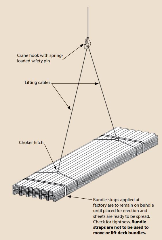
ERECTION OF DECK AND JOB SITE SAFETY
SAFE WORKING PLATFORM:
To make the working platform safe and prevent metal decking damage, the metal floor deck or metal roof deck (cubierta de metal) units should be attached to the frame and side laps connected as soon as possible. If the metal decking sheets are temporarily used to access bundles, they must be end bearing (not cantilevered) and must be securely attached to the frame to prevent slip off. A working area should be at least 12 feet wide. It is recommended that a working area be established around or along each metal roof decking or metal floor decking bundle so that the bundle can safely be accessed. The platform can then be extended in any convenient direction. Specific job requirements need to be considered to determine metal decking erection starting points and erection progression. As the platform is extended it will be necessary for at least one worker to work from the structural frame. OSHA standards require that employers provide fall protection during metal decking erection operations, and all OSHA guidelines for safety while erecting metal roof deck or metal floor deck must be followed. Refer to OSHA Regulation 29 CFR Section 1926.759(c)(2003) which states that under special circumstances a Controlled Deck Zone (CDZ) may be established which permits flexibility to the methods of personal fall protection.
PLACING DECK:
As the deck sheets are placed, one edge of deck will always be “Open” or leading. This leading edge should only be approached in order to place the next sheet. Workers should also maintain a safe distance (6 feet if possible) from the end of the metal roof deck or metal floor deck unit. When aligning the edge (side) lap, the worker should kneel. Kneeling lowers a worker’s center of gravity and decreases the change of falling. Refer to OSHA Regulation 29 CFR Section 1926.759 (a)(1)(2003) which states that under special circumstances a Controlled Deck Zone (CDZ) may be established which permits flexibility to the methods of deck installation.
Roof and floor holes and openings should be decked over, unless the size of the hole or special design circumstances prevent it form being decked over. It is the responsibility of the design professional to define whether a hole is required to be decked over. Where large size holes or other conditions that do not allow an opening to be decked over, employees shall be protected in accordance with OSHA Regulation 29 CFR Section 1926.760 (a)(1)(2003).
OTHER TRADES:
Other trades should be kept off the working platform and the area immediately below the working platform during the metal decking erection process. Care must be taken when cutting bundle straps to prevent straps or dunnage from dropping onto personnel or equipment. Workers should be instructed on all aspects of deck safety before any metal floor decking or metal roof decking is installed. Such installation is available to members on request from the Iron Workers International Association (AFL-CIO) by contacting a local union training coordinator. Non-union sources may also be available.
Metal Floor Deck (suelo de metal cubierta) should be selected so that it provides at least fifty pounds per square foot capacity as a working platform. If temporary shoring is required to attain fifty pounds per square foot, then the shoring must be securel in place before the floor deck erection begins. The fifty-pound per square foot loading does not consider concrete weight.
Metal Roof Deck (techo de metal cubierta) is not generally required to carry as much foot traffic as metal floor deck, but at least thirty pounds per square foot should be made available by the metal roof decking. If the metal roof decking being used does not provide a platform capacity of 30 PSF, then it should be planked or supported during erection. Areas subject to traffic or material staging should be planked.
A steel deck surface is inherently slippery when wet. Caution is required by anyone on the deck when this condition exists.
SAFETY NOTES:
1. Make sure that rigging is adjusted to keep hoisted loads well balanced.
2. Do not stand under loads being hoisted.
3. Keep loads in view.
4. Use proper hand signals to crane operators.
5. Check erection drawings to land deck in proper position and orientation to avoid turning deck.
6. Make sure bundles are secure and stable before cutting bands.
7. Pay particular attention to single span bundles:
— A. Do not sure single span bundles as a working platform,
especially to cut bands
— B. Sheets should shift due to handling. Ensure bottom sheet
extends past the support at both ends, otherwise
place where full support can be obtained.
8. When cutting bands on bundles use both hands and stand well back – bands are under tension. Eye protection is recommended.
9. Pay special attention to short units or single span units — make sure the metal decking is firmly secured before using it as a working platform.
10. Make sure cut outs and openings are adequately supported and guarded.
11. Use chalk lines to locate supporting steel – measure accurately.
12. Be alert for sharp edges.
13. Wet deck is inherently slippery – watch your footing.
14. Keep a litter free work place.
15. Wear eye protection when near welding.
16. When installing galvanized metal decking on sunny days, sunglasses and sunburn protection are advisable.
17. STAY ALERT.
FASTENING AND INSTALLING METAL DECK:
Metal Decking (Cubierta de metal) is installed in accordance with the “Approved for Construction” drawings. The metal roof deck or metal floor deck must be installed by qualified and experienced metal decking worker / installers. The beginning point should be carefully selected for proper deck orientation and edge of roof or floor slab location.
Maintaining rib or flute alignment across the structure is very important. A snap chalk line should be used at reasonable intervals to assure proper alignment of deck panels. Panel cover widths must be maintained to achieve long straight runs of deck.
Metal roof deck (techo de metal cubierta) is often left exposed on the bottom. Rib alignment must be parallel to the girders at all girder lines to prevent unsightly conditions.
Metal floor deck (suelo de metal cubierta) flutes should, if possible maintain alignment to achieve continuous concrete ribs across abutting sheet ends, minimizing concrete leakage. Flutes that do not align can create closure problems that may interrupt the slab design. Proper alignment can only be achieved by proper adjustment of each deck panel as it is placed. Cover width errors accumulated across the bay cannot be corrected with the last sheets in the run.
On-site experience has demonstrated that the frequency of snapping a chalk line determines the accuracy of rib and flute alignment. This minor effort at the time of deck placement eliminates the need for field corrections.
For metal roof deck or metal floor deck to perform its design functions and serve as a working platform, it must be adequately and properly attached. Often the metal decking is used as part of the horizontal bracing system and the fastening method and pattern have been selected to provide a certain strength and stiffness in the plane of the metal deck.
NO SUBSTITUTION of fastener type or pattern should be made without the approval of the designer.
Metal deck (cubierta de metal) fastening to the structural frame can be accomplished with welds, self drilling screws, air driven, or powder driven fasteners. A minimum of 1-1/2″ of end bearing should be provided for metal roof decking or metal floor decking. If there is less than 1-1/2″ of bearing, additional fastening should be provided and the deck end load capacity should be checked. For metal decking that is intended to end lap (metal roof deck), the end lap location should be adjusted so the center of the lapped portion occurs over the support or, when supported by bar joists, over a top chord member.
Only qualified operators may use powder actuated tools; air actuated tools must be used by trained operators familiar with all safety procedures.
ATTACHING
Special electric screw guns are used to drive self-drilling screws to attach deck to the structural frame. These screw guns are equipped with a clutch and depth limiting nosepiece to prevent over torquing. Screws are typically #12’s or 1/4″ diameter with a special drill point selected according to the total thickness of metal (deck plus frame) being joined.
Air driven tools are operated at a pre-set pressure level consistent with the fastening requirements of the metal decking attachment. Air is supplied by a compressor equipped with a regulator that prevents over-driving or under-driving the fastener. The fasteners have a flat head at the drive end and a ballistic point at the penetrating end. A variety of sizes are available to meet the penetration requirements of the steel substrate.
WELDING
Welding must be done by a qualified welder during proper weather conditions. Quality welding of light gauge metal roof decking (techo de metal cubierta) or metal floor decking (suelo de metal cubierta) requires experience and the selection of proper amperage and electrodes. A weld quality control test procedure is shown below. All welding should be done in accordance with the Structural Welding Code, AWS D1.1 or D1.3. Weld washers are not recommended for deck thicknesses of 0.028 inches thick (minimum 22 gauge) and greater. Weld washers are recommended for metal thicknesses less than 0.028 inches. Proper welding requires good metal-to-metal contact; therefore, lapping composite metal floor deck units and shear lugs is not recommended. For the same reason, built in hanger tabs (in metal floor deck) that bear on structural steel should be flattened or removed.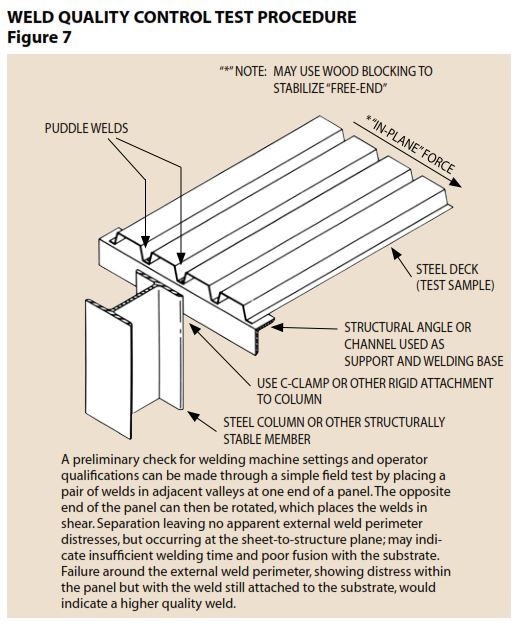
SHEAR STUDS
Shear studs, welded in place with special equipment (in accordance with AWS D1.1) can serve as welding to hold the deck to the frame. These studs are usually installed after the deck as been spread to act as a working platform. Therefore, it is necessary that the platform be adequately attached to the structure before the studs are installed.
Shear studs can be welded through the double metal thickness of cellular deck. Note: If the deck is heavier than 16 gauge the stud manufacturer should be consulted for installation procedures. Shear studs, like all other fasteners, must be installed in accordance with the design drawings.
Since most construction work is done in open air, ventilation for welding is usually adequate. However, for closed in areas, ventilation must be provided. Adequate ventilation is extremely important when welding galvanized metal decking. All workers involved in the welding operation must wear eye protection to avoid weld flash.
Welding should not be done near any type of combustible material. Cutting and welding sparks can cause construction fires. Conditions at a construction site are subject to rapid change. Welding may be safe in a given area and then, because combustibles are introduced, the area is suddenly not safe. The General Contractor (job supervisor) should prevent other trades from storing combustibles near or under areas where welding is to be done. Constant alertness in and below the general area is mandatory.
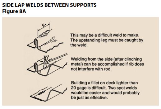
SIDE LAP CONNECTIONS
Sheet to sheet connections may be required at the side laps of metal decking. These are frequently referred to as stitch connections. Self drilling screws, welds or button punches are the usual stitch connections. Stitch screws are usually self drilling type; #8’s through 1/4 inch diameter can be used, but screws smaller than #10 diameter are not recommended. The installer must be sure that the underlying sheet is drawn tightly against the top sheet. Again, as when screws are used as the frame attachment, the special screw driving guns are used to prevent over torquing.
Manual button punching of side laps requires a special crimping tool. Button punching requires the worker to adjust his weight so the top of the metal deck stays level across the joint. Since the quality of the button punch attachment depends on the strength and care of the tool operator, it is important that a consistent method be developed. Automatic power driven crimping devices are rarely seen on metal deck jobs, but should not be ruled out as a fastening method. (Outdated: The Delta Grip Tool System is now a common, automatic, power driven crimping device used on many metal roof decking job sites).
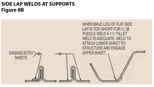
Good metal to metal contact is necessary for good side lap welds. Burn holes are the rule rather than the exception and an inspector should not be surprised to see them in the deck. The weld develops its strength by holding around the perimeter. A good weld will have 75% or more of its perimeter working. On occasion, side lap welds will be specified for metal decking that has the button punchable side lap arrangement. Welding side laps is not recommended for metal decks type 22 gauge (0.028″ inch minimum) or lighter. Weld washers should never be used at side laps between supports. Just as when welding to the frame, adequate ventilation must be available and welding near combustibles prohibited.
HOUSEKEEPING
Bundling straps, wood dunnage, and deck cut offs should be collected and removed from the working platform daily so as not to create a safety hazard underfoot. Loos tools should not be left lying about. Stud welding ferrules should be broken off of the studs. All debris must be removed from metal floor deck before concrete is poured.
All parties concerned with the construction process should cooperate to properly store combustible material and remove trash that can be a fire hazard.
Absolutely no loose metal roof deck or metal floor deck sheets should be left at the end of the working day. Any partially used bundles must be tightly secured to prevent blow off.
DECK DAMAGE AND PENETRATIONS
Damage to deck and purposeful penetrations have much in common: their location and severity are seldom known beforehand. Usually the design professional knows the general area where a vent stack may cut the roof, or approximately where a telephone conduit may pierce the slab; but he may not know how big the hole will be. This lack of information makes it difficult to advise how holes should be reinforced, if at all, or how damaged deck should be repaired. Guide specifications reflect this lack of specific knowledge. The SDI Specification states, “Openings not shown on the erection diagrams, such as those required for stacks, conduits, plumbing, vents, etc., shall be cut (and reinforced, if necessary) by the trades requiring the openings.” The design professional should be consulted for reinforcing requirements, but frequently, unless details are shown on the plans, no deck reinforcing is provided and the design professional is not consulted.
Deck damage presents similar problems. Broad statements such as, “All damaged deck must be replaced,” can be made. The design professional must then make the decision as to what constitutes damaged deck while considering how replacement may delay the job. How much damage can be tolerated depends on architectural and structural considerations. If the underside of the deck is exposed to public view, very little visible damage may be allowed. In most cases, however, the deck will be hidden by a ceiling or ducts and utilities and the usual concern is about structural performance.
ROOF DECK (techo de metal cubierta):
For most 1-1/2″ metal roof decks the loss of one rib per sheet, either by denting or penetration, can be tolerated. No reinforcing is generally required for an opening of 6″ as long as not more than two webs are removed. In most cases, the capacity of the deck is greater than required for roof loads. One six inch diameter hole per sheet in a span should not adversely affect the diaphragm strength, and a dent can be larger than 6″ and still carry the horizontal load. Covering a dent or an 8″ maximum hole with a 0.045″ plate and extending the plate to adjacent ribs could eliminate worries about insulation board spanning the dent and about a “soft spot” in the roof. For holes or dents greater than a rib (8″ to 13′), it is advisable to use a 0.057″ minimum plate. Exceptions to this recommendation are:
1. The hole may be located in such a place that the deck can safely cantilever from each adjacent support;
2. A group of holes may be so close together that a structural frame is required.
SUMP PANS:
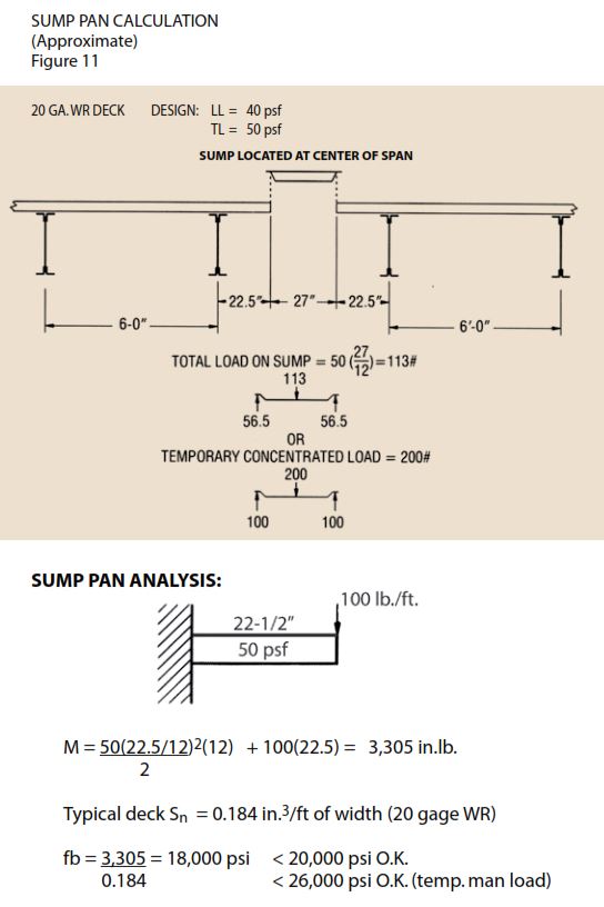
A special case of roof penetration is the sump pan. When properly attached, the sump pan will care the load of the deck it replaces. It also acts as a small header to transfer loads into adjacent uncut sheets. Approximated per foot (of width) section properties of a standard (0.075″) sump pan are: I=0.36 in(4); Sp=0.20 in(3). Approximated sump pan analysis methods, and a reinforcing technique are shown below.
Burn holes in metal decking side laps, caused by welded side lap attachments, are spaced far enough apart not to cause problems. Burn holes near intermediate supports are unlikely to cause much loss of strength unless a total area greater than a 6″ diameter hole is removed. These burn holes are usually caused by the welder searching for the unseen structural member; therefore the use of chalk lines is recommended.
Distributed small dents, such as those caused by foot traffic, will not cause a structural problem; but if the denting covers a large percentage of the job, the insulation board will be better attached with mechanical fasteners rather than by adhesives. The design professional must approved any change in fastening.
Vigilance should be maintained to detect correct any “soft” sports in roofs that could cause insulation boards to crack under foot loading.
FLOOR DECK (suelo de metal cubierta) :
Before concrete is poured, the contractor should inspect the deck to find any areas that may be damaged or crushed which may require shoring for the concrete pour. Areas that buckle during the pour are usually caused by previous damage, over spanning the deck, or allowing concrete to pile up. Buckled areas do not adversely affect the live load capacity. Tests at West Virginia University, by Dr. Larry Luttrell, showed no loss in live load capacity when the deck was purposely buckled.
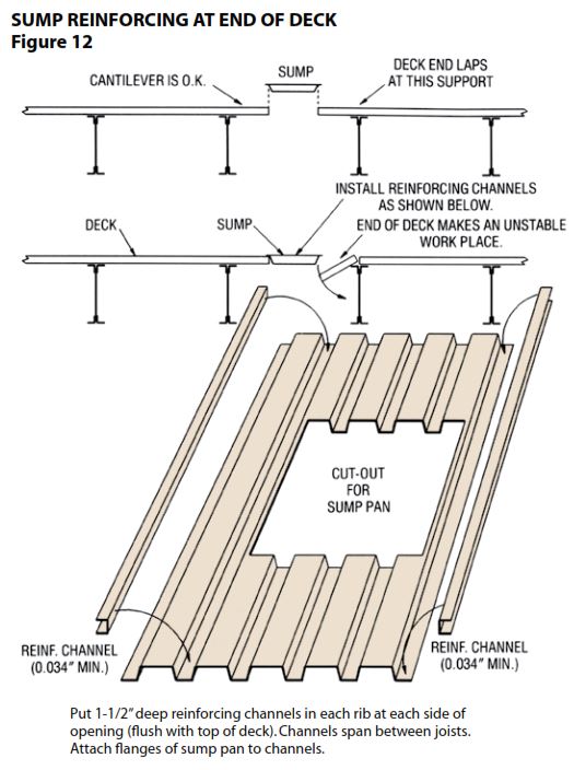
Since floor deck damage or penetration can affect the metal decking’s capacity to carry concrete, any metal floor deck damage or penetration must be evaluated prior to pouring concrete. Metal floor deck, like metal roof deck, can be examined as a cantilever. However, the SDI does not publish a cantilever table for metal floor deck because of the great profile variations available. A method for calculating allowable cantilever spans is shown below. A preferred forming method is to block out concrete from where a penetration will occur; and, after the concrete sufficiently cures, burn the deck away. The design professional determines the need for additional bars or mesh around the block out.
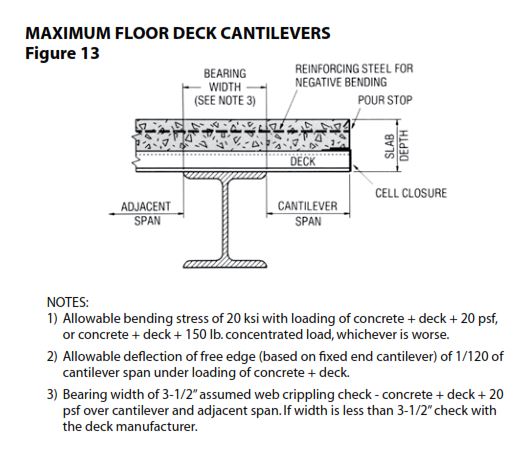
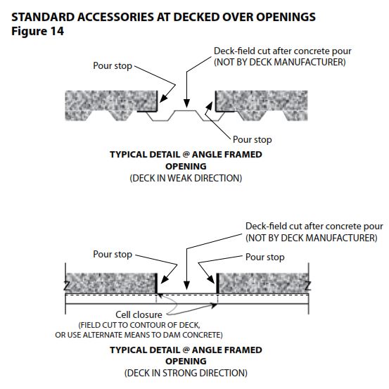
It is the responsibility of the design professional to designate holes/openings to be decked over in compliance with OSHA Regulation 29 CRF Section 1926.754(e)(2)(2003). When a hole/opening is not shown and dimensioned on the structural design drawings, no provisions for concrete retainage will be provided. When a framed hole/opening is shown and dimensioned on the structural design drawings in floor deck, pour stop (screed) angle will be provided from the top of the deck to the stop of the slab only. Cell closures will be provided in strong dimension in standard 10′-0″ lengths to be field sized, cut and installed as shown below. Do not field cut deck at holes/openings until concrete has reached 75% of its design strength (minimum seven (7) days in most cases).
The deck should be inspected for adequate attachment at supports and at side laps. Side laps must be tightly connected to prevent opening during concrete pouring.
Concrete provides an alkaline environment that discourages corrosion. Since most applications of composite metal floor deck are in dry interior areas, field painting of burned, cut or abraded areas is not usually required. Any touch up requirements must be provided in the job specifications since the design professional establishes the deck finish required for the environment.
PLACING CONCRETE:
After the metal floor deck (or form deck) has been properly installed, it acts as a working platform for many trades. The deck should have been selected to provide at least fifty pounds per square foot capacity as a working platform. If the contractor anticipates loads on the platform that will exceed 50 psf, they should take appropriate steps to ensure the deck will carry the load.
Before concrete is poured, the contractor should make sure that the deck is properly and completely fastened in accordance with approved deck erection drawings and the deck has adequate bearing on all supports. Damaged areas must be repaired or accepted. All ferrules should have been broke off the studs. All dirt and debris must be removed. All reinforcement, wires or rods, should be securely in place. The concrete contractor should review the deck shoring requirements and make sure that shores are securely in place.
Concrete should be poured from a low level to avoid impacting the deck. It should be placed uniformly over the supporting structure and spread towards the center of the deck span. Concrete should be placed in a direction so that the weight is first applied to the top sheet at the side lap, reducing the possibility of the side opening during the pour. Workers should not congregate around the concrete placement zone. If buggies are used to place the concrete, runways should be planked and the buggies should only operate on the planking. The planks should be stiff enough to transfer buggy loads without damaging the deck. Deck damage caused by roll bars or careless placement must be avoided.
Quality Metal Decking — 2227 Dunn Road, Hayward, CA 94545 — (510) 887-2227
We ship nationwide. All our roof deck (1.5″ deep B-36 and 3″ deep N-32) and floor / composite deck (1.5″ deep BH-36, 2″ deep 2WH-36 and 3″ deep 3WxH-36) can ship to all 50 states.